
In this tutorial we will perform a physical optics propagation through the same optical system as the previous tutorial.
We start by loading our saved system from the previous tutorial. From the Systems menu we select Load system

In the previous tutorial we purposefully oversized the off-axis paraboloid reflector for illustrative purposes. This time, we size the paraboloid in such a way that the illuminating beam has an edge taper between -10 and -15 dB.
We remove the paraboloid from the element options in the workspace:

and we add a new paraboloid:
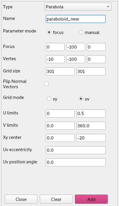
We do the same to the tilted plane. We remove the old one, increase the gridsizes from 101 by 101 to 301 by 301 and reduce the radius from 10 mm to 5 mm.
If we do not do this, the beam pattern we obtain on the paraboloid is undersampled coming from the tilted plane and we would see nonsensical results.
We have also replaced the ellipsoidal mirror with a new one, with gridsizes of 279 by 279 (just like the one in the Jupyter notebook tutorial 3) an have reduced the radius to u = 10 mm. It is important to check the Flip Normal Vectors box, because we are illuminating the ellipsoid from below.
Next we define a circular plane (by giving it uv limits rather than xy) in the upper focus of the ellipsoid. This will serve as the focal plane of our ellipsoid on which we define the initial beam pattern.
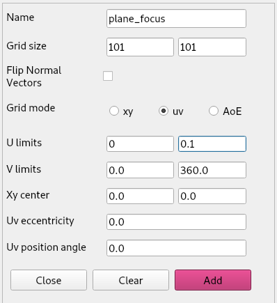
Before translating our plane to position, we define a Gaussian beam on it. This is important as the Gaussian beams are always defined with their focus in the origin.
From the Physical-optics menu we select initialize beam > Gaussian beam > Vectorial and we fill in the form as such:
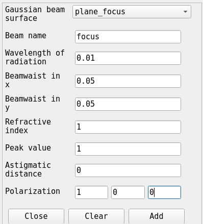
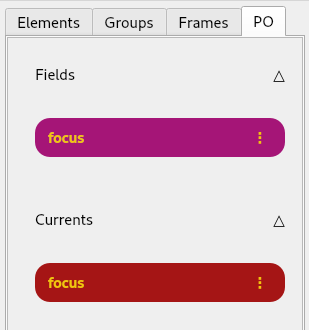
After clicking Add beam we can see that a field and a current have been added to the PO tab of the workspace.
Now we can translate our plane_focus with 100 mm along the z-axis.
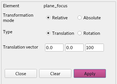
Now we can propagate our beam through the system. From the
Physical-optics menu we select Propagate beam > To
surface. Then we perform the following propagations
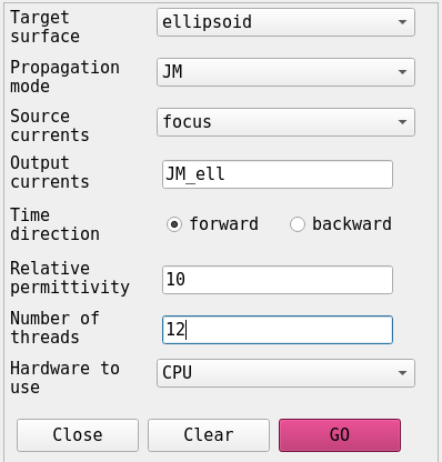
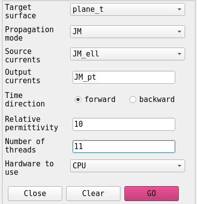
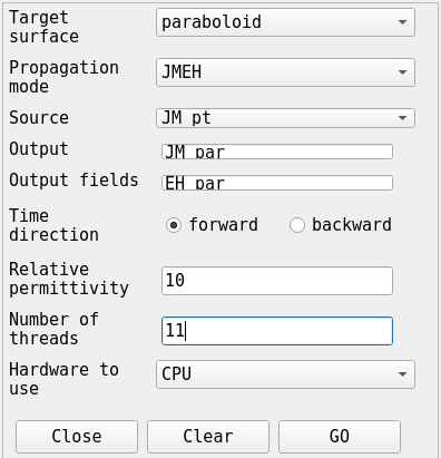
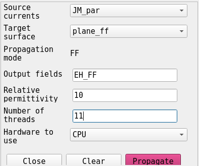
We set, for the first two propagations, the ‘mode’ parameter to ‘JM’. This means we only store the calculated JM currents on the target surface. If we specify ‘EH’, such as for the last propagation, we only save the illuminating field on the target surface. If we want both, we specify ‘mode’ as ‘JMEH’. Another option, ‘FF’ for far-field, will be explained in more detail below. The last option, ‘EHP’, stores the reflected field and corresponding Poynting vectors. With this option it is possible to do a combined ray-trace and PO approach. This is not explored further in the GUI tutorials, but is explained in the fifth Jupyter notebook tutorial “PO efficiencies and metrics”.
Now we can plot the beam that we propagated through the system onto the paraboloid.
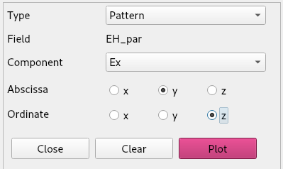
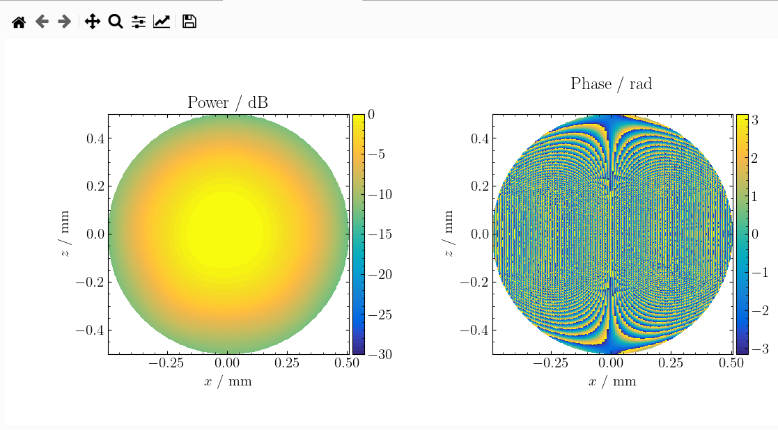
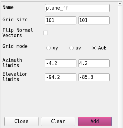
We can create a far-field element by adding a plane and setting its grid-mode parametrization to AoE (Azimuth-over-Elevation). Then we propagate the field from our field EH_par to this far-field element. This can be done from the Physical-optics menu by selecting Propagate Beam > To far-field.
If we now plot the generated EH_FF field, it looks like
this:
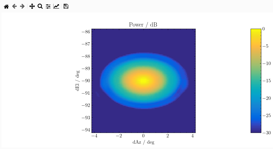 Which is the same pattern as the far-field pattern calculated in the
third Jupyter notebook tutorial.