In PyPO, there are two common ways to parameterise the surface of a reflector. On this page, we will explain these two parameterisations in more detail. Also, there is a third parameterisation for PyPO, which we will discuss.
The Cartesian, or "xy", parameterisation is the most straightforward parameterisation in PyPO. For quadric surfaces it consists of selecting a patch of x and y co-ordinates and evaluating the expression for the quadric surface on this patch in the xy-plane. This generates the z co-ordinates corresponding to the x and y co-ordinate in the xy-plane. For planar geometries, it is even simpler as the z co-ordinate for all x,y in the xy-plane is set to zero.
For a general reflector, the "xy" parameterisation is toggled by passing "xy" to the "gmode" field in a reflector dictionary. After setting this, it is important that the following two fields are also set:
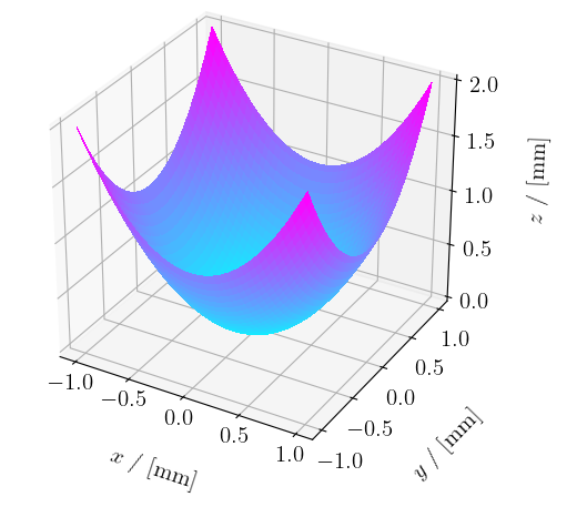
See image below for a paraboloid with "gmode" set to "xy" and "lims_x" and "lims_y" both set to numpy.array([-1, 1]). The "pmode" is "manual", with "coeffs" set to numpy.array([1, 1]).

The next parameterisation is the polar, or "uv", parameterisation. This parameterisation first takes a (rectangular) patch in the uv-plane, and converts it to a (circular) patch in the xy-plane. The u co-ordinate is the radial part and the v co-ordinate the angular part. Then, the procedure goes along the same lines as for the "xy" parameterisation. This parameterisation is more appropriate for symmetric surfaces of revolution, due to the rotational symmetry present in the parameterisation and reflector.
For a general reflector, the "uv" parameterisation is toggled by passing "uv" to the "gmode" field in a reflector dictionary. After setting this, it is important that the following two fields are also set:
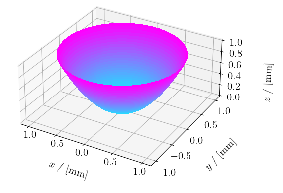
See image below for the same paraboloid with "gmode" set to "uv" and "lims_u" to numpy.array([0, 1]) and "lims_v" set to numpy.array([0, 360]).

When the "uv" parameterisation is selected, three optional fields become available:
These options are not (yet) available for the "xy" parameterisation.
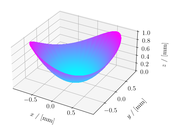
Of these options, the "gcenter" option plays a special role. Using this field, it is possible to generate off-axis reflectors from a circular xy patch. This is interesting from the perspective of, for example, radio telescope designers, as off-axis designs have the advantage of having less feed/secondary support strut blockage.
See image below for the same paraboloid with "gcenter" set to numpy.array([0.5, 0.5]).

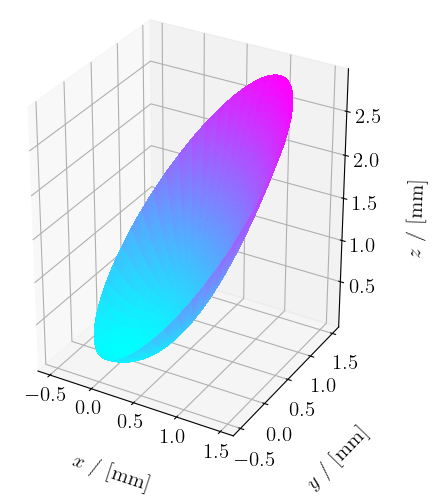
See image below for the same paraboloid with "ecc_uv" set to 0.7 and "rot_uv" set to 45 degrees. The "gcenter" is set to the origin again.

The final parameterisation type is the Azimuth-over-Elevation, or "AoE", parameterisation. This parameterisation is exclusive to planar geometries. The parameterisation is necessary for defining far-field elements. When a far-field beam pattern is calculated on an "AoE" parameterised surface, PyPO internally converts the Azimuth and Elevation angles to direction cosines on-sky and calculates the far-field.
In order to define a plane in the far-field, set the "gmode" field to "AoE" and make sure the following fields are present in the reflector dictionary:
Note that the grid generated by this parameterisation is angular instead of spatial. Translating this grid therefore does not displace it, but rather changes the direction in which the far-field is calculated.
Before a reflector dictionary is accepted by the System, one final field needs to be specified: the "gridsizes" field. This field is a Numpy array of length 2 and defines the amount of cells along the x/u/Az and y/v/El axes. This field is therefore very important, as using values that are insufficiently accurate might result in nonsensical results. the best way to find good values for this field is by experimenting a bit and seeing what works through trial-and-error, because finding a rigorous one-stop solution for determining this is relatively hard.
PyPO does contain an aid, however, in the form of the autoConverge() method, present in System. For this method to work, a PO field should be present as well as the target surface onto which the field is to be propagated. This method is still quite experimental, but has shown to work relatively well in the few situations it has been tested. Nevertheless, the "gridsizes" field should be set carefully, and users should investigate the correctness of their simulation by tweaking these values yourself.